
Tmteck Angle Beam Transducers Introduction
Angle beam inspection
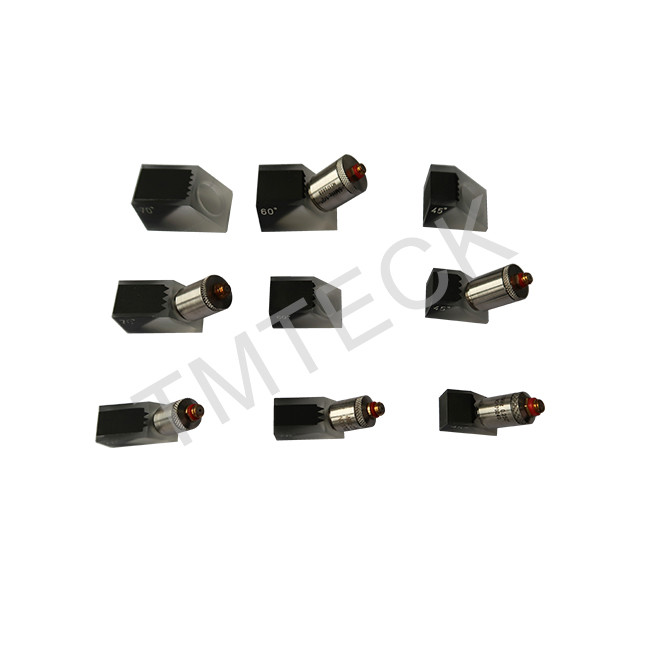
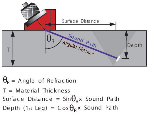
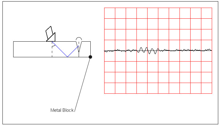
The angle-beam (Shear Wave) technique is used for testing sheet, plate, pipe, & welds. A plastic wedge is placed between the test object and the transducer with a film of couplant between the transducer and wedge. The plastic wedge permits the sound wave to enter the test object at an angle. The sound-beam is then reflected back to the transducer as in straight-beam testing.
Angle beam inspection 2
Often straight beam testing will not find a defect. For example, if the defect is vertical and thin enough, it will not reflect enough sound back to the transducer to let the tester know that it exists. In cases like this, another method of ultrasound testing must be used. The other method of ultrasound testing is angle beam testing. Angle beam testing uses an incidence of other than 90 degrees. In contact testing, an angled plastic block is place between the transducer and the object to create the desired angle. For angle beam testing in immersion systems, a plastic block is not needed because the transducer can simply be angled in the water.
 |
 |
 |
 |
If the angle of incidence is changed to be anything other than 90 degrees, longitudinal waves and a second type of sound wave are produced. These other waves are called shear waves. Because the wave entered at an angle, it does not all travel directly through the material. Molecules in the test object are attracted to each other because solids have strong molecular bonds. The molecules carrying the sound are attracted to their surrounding molecules. Because of the angle, those sound carrying molecules get pulled by attracting forces in a direction perpendicular to the direction of the wave. This produces shear waves, or waves whose molecules travel perpendicular to the direction of the wave.
Angle beam testing and a change in the angle of incidence also creates further complications. Remember that when a wave hits a surface at an angle, it will be refracted, or bent, when it enters the new medium. Thus, the shear waves and the longitudinal waves will be refracted in the test object. The amount of refraction depends on the speed of sound in the two mediums between which the wave is traveling. Since the speed of shear waves is slower than the speed of longitudinal waves, their angles of refraction will be different. By using Snell’s law, we can calculate the angle of refraction if we know the speed of sound in our material.
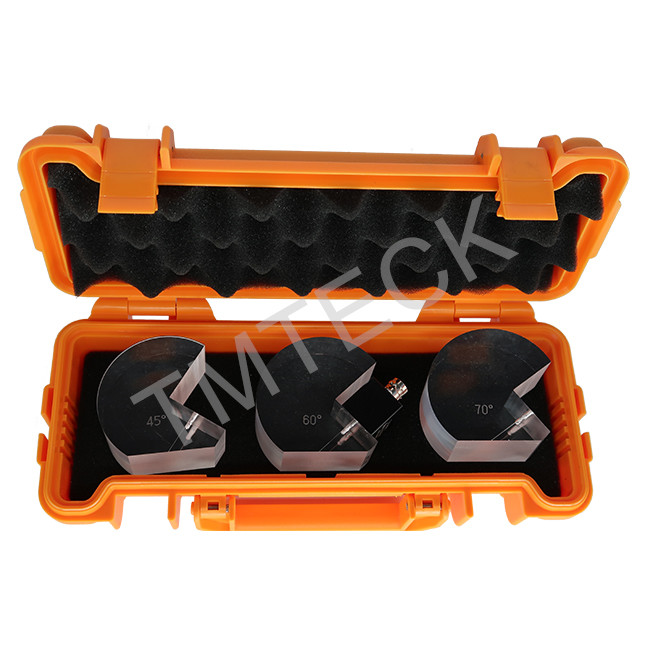
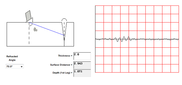
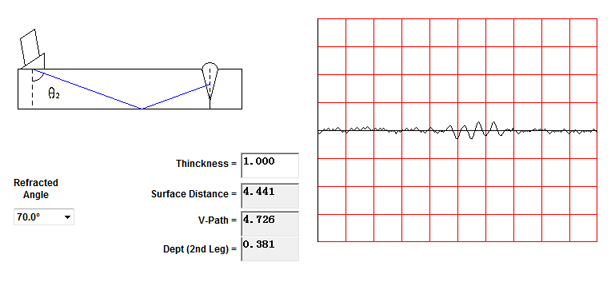
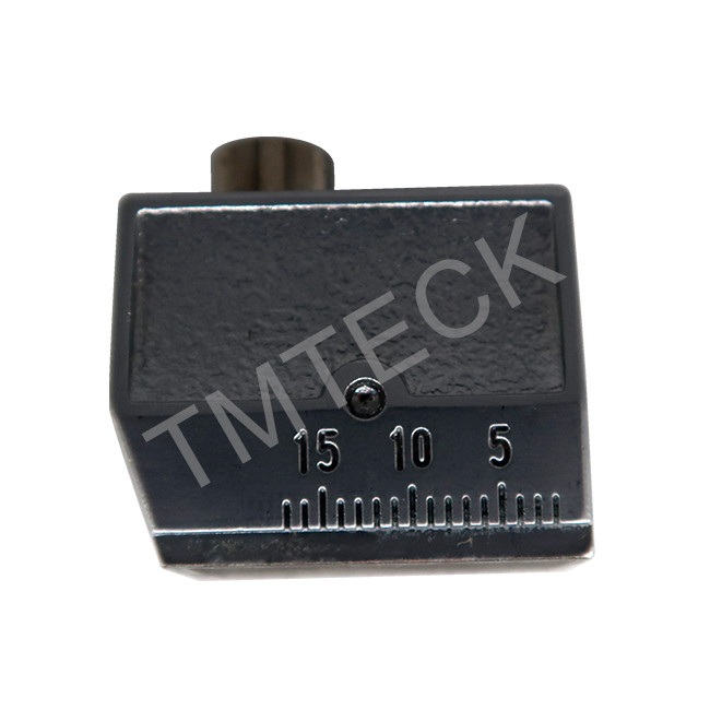
An angle is selected to ensure that an echo is obtained from suspected flaws. These are often the most detrimental flaws, e.g. lack of fusion on welded sidewalls and at the root, or cracks. The probe angles most generally used for varying thickness of steel are as follows:
a. 70 Wedge – 0.250 to 0.750 inches in thickness
b. 60 Wedge – 0.500 to 2.00 inches in thickness
c. 45 Wedge – 1.500 and up in thickness
Probes operated at other angles have to be used, dependent upon the position of the flaw in the material under test, and for special cases in thinner sections. The frequency should be sufficiently low so as to avoid excessive attenuation.
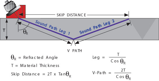
Angle Beam Transducers and wedges are typically used to introduce a refracted shear wave into the test material. An angled sound path allows the sound beam to come in from the side, thereby improving detectability of flaws in and around welded areas.
Post time: Sep-26-2021